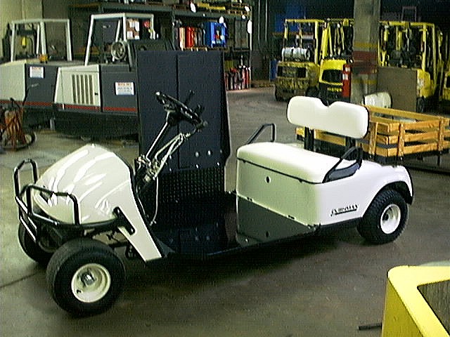
Somehow Robert found us. I'll have to ask him, the next time I see him, how he did that. It certainly was not from our lovely company web site! He wanted an electric vehicle that he could drive around on his farm. KDI and Robert struck a deal. The next thing I knew about this, a new Bellhop 4 arrived at work. KDI said, "Uncrate this, and remove the front seat assembly." Say WHAT? Therein lies the beginning of a mystery...
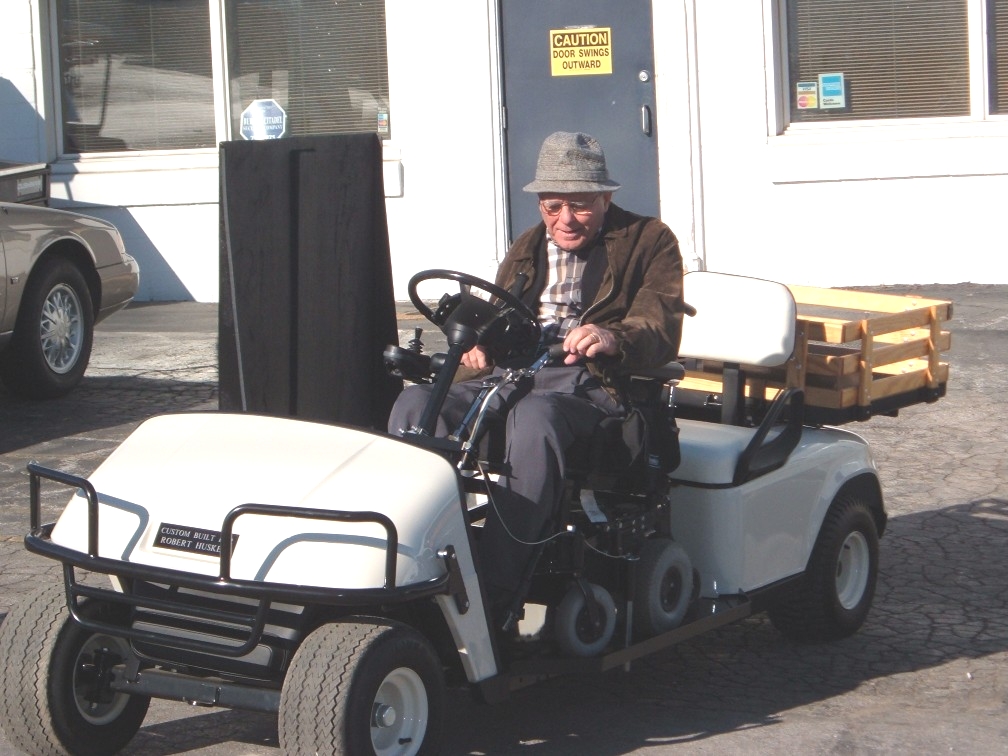
Maybe you can see where this leads to... I could hardly wait until we could really get going on this project.
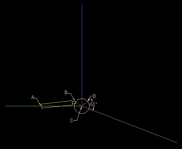
I asked a Civil Engineering friend (Thanks Bob!) how the ramp mechanism might be configured. Here's what he came up with:
"Green line: floor of Bellhop
Pink/red line: lowered ramp
Purple line: raised ramp
Point A: anchor point for actuator
Points B & D: attachment point (to ramp) for actuator
Point C: hinge
The distance between points B and D is about 5.75"; corresponding to
the hydraulic ram's travel.
The "arm" that lifts the ramp is 3.75" long. Anything longer will
exceed the travel of the ram.
I show the arm at an angle of 61 degrees from the ramp. That's not as
exact as it might seem. It just looks like the "right" angle for
lifting the ramp, and getting the most out of the actuator.
The circle is just a guide to help me size the arm. (7" d)
Based on the lengths and weights you provided, it looks like you will
need about 45 ft-lbs of torque to raise the ramp through its horizontal
position.
The actuator will need to be able to pull about 240 lbs of force to
lift the ramp. You could do it with less force if you increased that
61 degree angle, but then you would not have much mechanical advantage
when the ramp approaches its raised position. It's still worth looking
into."